A live centre is bought on three things, and only one of them is printed on the record
This page is about picking the centre that goes in the tailstock, not about the chuck at the other end. The A4 guide covers the pair working together and where the concentricity error comes from; the A3 guide covers the order in which runout is traced at the tool end. Here the question is narrower: a shaft is going between centres, the tailstock is free, and one part has to be chosen from a catalogue whose numbers do not all mean what they look like.
The point is blue and the dial says the centre is new
A long shaft, 40 mm at the diameter, turned between centres. Halfway through the finish pass the surface starts to pick up a helical mark, the point of the centre goes from bright to straw to blue in two parts, and the diameter at the tailstock end grows while the chuck end holds. The centre is a month old. The dial on the body reads what it read when it was new. Nothing about the tool or the programme has changed. The thing that changed is that the load arriving at the point is no longer being carried where it was designed to be carried, and the evidence is a colour.
That is the shape of most live-centre problems. The part is not wrong because the centre is worn out; it is wrong because the centre is being asked to do something the geometry of the joint does not support. Three separate things decide whether it can: the angle at which the cone meets the centre hole, the path the load takes from the point into the bearings and out through the taper, and the plane in which the runout figure was measured. Only the last of those is a number on a record, and even there the record does not say which plane.
The point angle decides where the contact sits
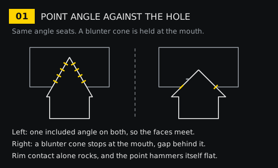
A centre hole is not a hole. It is a cone, cut by a centre drill, and the centre that enters it is a cone of the same family. When the two included angles agree, the surfaces lie on each other and the load crosses the joint along the whole chamfer. When the centre is blunter than the hole, the cone is stopped by the mouth of the hole: the two surfaces touch on a ring at the rim, and the gap between them grows toward the apex. When the centre is sharper, it bottoms at the small end and the chamfer carries nothing at all.
Both mismatches look identical from outside the machine. The part turns, the centre is not obviously loose, and the first sign is a mark on the work or a point that discolours. The rim-contact case is the worse of the two, because the ring is small, the pressure on it is high, and the centre can rock within the mouth under an interrupted load. A point that rocks hammers its own surface flat, and a flattened point spreads the contact further, which is why the discolouration appears as a band rather than a spot.
Two loads arrive at the same point and leave by different roads
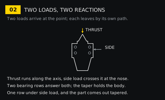
The tailstock pushes along the axis; that is thrust, and it is the load the centre is built around. The part also pushes across the axis, through its own weight on a long shaft, through the radial component of a turning cut, and through whatever the part does when it is out of balance. That is side load, and it is the load that decides whether the point stays where it was set.
The two loads are carried by different parts of the same body. Thrust goes into the bearing rows and is reacted by the tailstock quill. Side load goes into the same rows as a radial force and then out through the body into the taper, which is held by the socket. A centre with one row of bearings can carry thrust and a little side load; a centre with two rows, spaced apart along the axis, resists the tipping moment that side load creates. That spacing is the reason a heavier centre deflects less at the same load, and it is also the reason a heavier centre is heavier.
The practical consequence is that the deflection at the point is not a property of the point. It is a property of the distance between the rows, the preload in them, and the fit of the taper in the socket. A centre that measures true on the bench and deflects under cut is telling you about the second and third of those, not about the first.
The taper is the side-load road, and it has to be clean
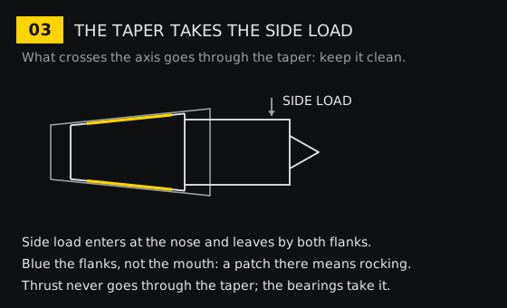
The taper does two jobs and only one of them is obvious. It locates the centre on the machine axis, and it carries the side load out of the body into the quill. Both jobs depend on the same thing: contact along the flanks, over as much of their length as the socket allows. A taper with a bright patch at the mouth and nothing further in is not seated, it is wedged, and a wedged taper rocks under side load in a way that a seated one cannot.
This is checked with bluing and it takes a minute. Clean the shank, wipe the socket, blue the shank lightly, seat it with a firm push and a quarter turn, take it out and read the pattern. Contact along both flanks from the big end toward the small end is what a good seat looks like. A ring at the mouth, a stripe on one side, or a pattern broken in the middle are all reasons to stop and look at the socket before blaming the centre.
The same test explains a failure that gets attributed to bearings. A chip or a burr on the shank lifts one flank off the socket, the body sits at a small angle to the machine axis, and the point orbits. The dial on the body shows it, the part shows it, and the bearing is innocent. The arbor taper guide goes through the same logic for a toolholder, where the consequence is a cutter running off centre instead of a part coming out tapered.
A runout figure belongs to one plane, and the record does not name it
In the 89 records of this category, the Precision field is filled 16 times and the Accuracy field 25 times. Twelve of the Precision values read 0.005mm, eleven of the Accuracy values read 0.010mm, five read 0.05 mm, three read 0.005mm and two read 0.008 MM. Those are four different populations of number sitting in two fields that a buyer reads as one property.
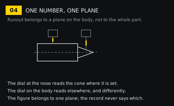
A runout figure is meaningful only with the plane it was taken in. The same centre can read one value with the dial on the cone a few millimetres from the nose, a larger value with the dial on the cone near its base, and a different value again with the dial on the body. Every one of those is an honest TIR reading of the surface under the plunger. None of them is a statement about the others, and none of them describes where the point will sit when the centre is under load.
So the useful question is not "is 0.005mm good" but "0.005mm measured where, against what, with the centre mounted or on a bench". A figure taken on a bench between centres, with no tailstock in the picture, tells you about the centre. A figure taken in the machine tells you about the centre and the socket together, which is the number that matters and the number no record carries.
The weight field is the part on a scale, not the load it can take
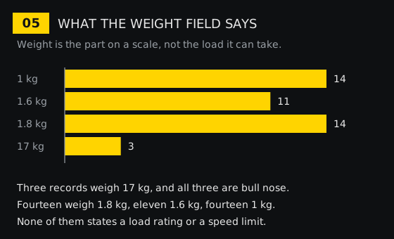
The weight field is filled in 59 of the 89 records and blank in 30. The values cluster: 1 kg appears 14 times, 1.8 kg 14 times, 1.6 kg 11 times, 2 kg 4 times, 5 kg 3 times, 17 kg 3 times, 3 kg twice, and then single records at 0.1, 0.3, 0.9, 2.3, 10, 30 and 60 kg. Read as a family list it makes sense: the light end is the half-notched and dead centres, the middle is the medium-duty and multi-purpose families, and the top is the bull nose.
What the field does not do is tell you what the centre will carry. A mass on a scale is not a thrust rating, not a radial capacity and not a maximum speed. No record in this category states any of those three, and the number that looks closest to a capacity, 17 kg, is the mass of a bull-nose body that also happens to be the one with the largest nose. The correlation is real; the inference from mass to capacity is not, and the two get confused because the heavier centre is usually the stronger one.
When the bull nose is worth the step up
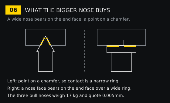
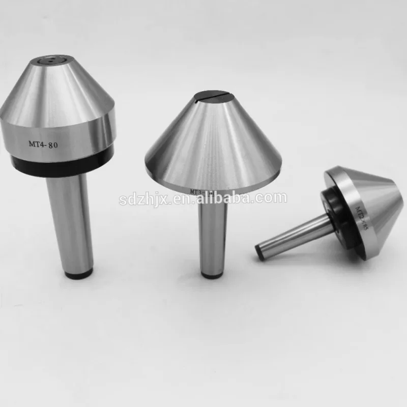
All three bull-nose records in this category weigh 17 kg, quote 0.005mm for Accuracy and HRC40 for Hardness. The number that matters is not in that list. It is the diameter of the nose, which is what turns a line contact on a chamfer into an annular contact on the end face of the part. A face contact at a large diameter resists the tipping moment directly instead of through the bearing rows, which is why a bull nose holds a heavy or hollow part that a point cannot hold steady.
That is the case where the step up pays for itself: a part with a large bore or a wide end face, where the centre hole is small relative to the mass, where the part is short and stiff and the cut is heavy. The step up costs mass, a longer nose that eats into the working length, and a face that has to be square to the axis or the contact becomes a line on one side. A bull nose on a part with a tiny end face is a heavy centre doing a small job, and the extra bearing capacity never gets used.
The notch, and the tips you can replace
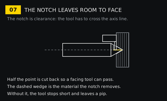
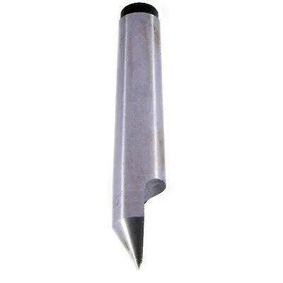
Eleven records here carry the name Half-notched Center, all at 1 kg and all quoting 0.010mm for Accuracy. The geometry is simple: one half of the point is cut back so a facing tool can reach the end face and cross the axis without touching metal. The trade is obvious once it is stated. Half the point means half the bearing surface on the chamfer, so the load per unit area doubles, and a half-notched centre belongs on parts that are faced in the same setup rather than on parts that are turned for an hour.
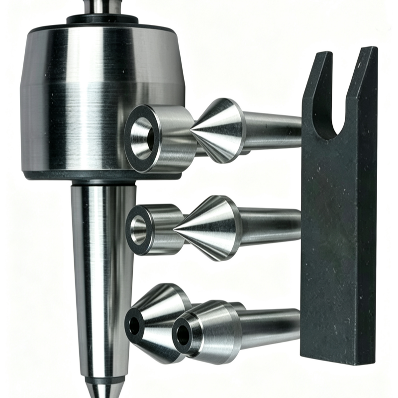
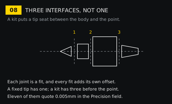
The eleven multi-purpose records weigh 1.6 kg and quote 0.005mm for Precision, and they carry a set of interchangeable tips. On paper that is the flexible choice: one body, several noses, a tip replaced when it is worn instead of a whole centre. In the machine it is one more interface, and an interface is a place where runout is added rather than removed. The tip seats on a taper inside the body, the body seats on the quill, and the two errors do not cancel.
A kit is the right answer when the work varies, when a damaged tip would otherwise take a whole centre out of service, and when the tips are sold as spares. It is the wrong answer when the job needs the smallest runout the catalogue offers, because the figure quoted for the body cannot include an interface that is chosen later. Ask what the tip alone costs and whether it is available before the flexibility is counted as a benefit.
What these 89 records promise, and what they do not
The category holds 89 records. Forty-three come from the live-centre image set and 46 from a general accessories import, and 36 of the 89 have no centre in their name at all: a brass pipe fitting, a pergola bracket, a deburring tool, a collet chuck, an edge finder. The top-level type reads Live Center on every one of them, which is a category label doing the work of a product description.
The fields follow the same pattern. Taper Size is filled in three records, while 23 names carry an MT number in their title, so the taper is in the name and not in the field. The point angle appears once in the whole category, on a centre drill that lists 120° and 60°, and never on a live centre. Hardness is filled 23 times with values from HRC40 to HRC 65, four of them HRC40 on the bull noses, and the rest spread across chucks, sleeves and inserts that are not centres.
None of that is a reason to distrust the catalogue. It is a reason to read it as a catalogue: the numbers describe what will arrive, not what it will do. The taper comes from the name, the family comes from the Product name field, the mass comes from the weight field, and the runout comes from whichever field the maker used and whichever plane the maker chose. The record-reading guide makes the same point about a different category, and the discipline is identical.
Five checks, in this order
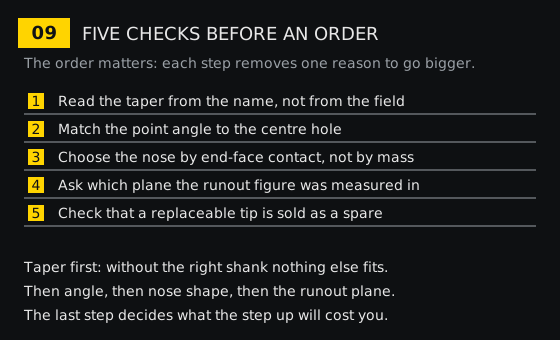
- Read the taper from the name and confirm it against the tailstock. Taper Size is filled three times in 89 records and the name carries it 23 times, so the name is the field that works.
- Match the point angle to the centre hole, and blue the point after the first part to prove that the contact is on the chamfer and not on the mouth.
- Choose the nose from the end face, not from the mass. A wide face at a large diameter is what a bull nose sells; if the part cannot present one, the nose is doing nothing.
- Ask which plane the runout figure was measured in, and re-measure in the machine with the taper seated, because that is the number the part will see.
- If the tip is replaceable, confirm that it is sold as a spare and that the seat is clean before the first cut. An interface that cannot be renewed is a wear item with no replacement.
The last check is the one that decides whether the flexible centre stays flexible after a year. Everything above it is geometry, and geometry can be measured on the machine in an afternoon. What cannot be recovered is a centre whose only tip is worn and unavailable, which is why the question belongs in the order rather than in the stores.
Related reading and the parts named here
The A4 guide covers the two ends of the same shaft and what happens when the chuck and the centre disagree. The A3 guide covers the order in which runout is traced at the tool end, which is the same order used here at the tailstock end. The category itself is Live Center, and the holders that sit at the other end of the spindle are under Collet & Holder.
The parts cited above are the bull-nose family in MT2 to MT5 at 17 kg, the multi-purpose kit with interchangeable tips at 1.6 kg, the half-notched centre at 1 kg, the medium-duty centre at 1.8 kg, the water-proof MT4 and MT5 centre with an oil hole at 3 kg, and the DG2 dead centre at 1 kg. Send the centre hole size, the part mass and the operation and the three can be checked against the geometry in one reply.