Choosing a controller for a retrofit: what has to match before anything is wired
The drives are still good. The iron still cuts straight when a part is indicated in. What died is the control in the cabinet, and the question is not which controller is better but which one can be connected to the six things already bolted to the machine: the drives, the handwheel, the spindle inverter, the tool changer, the limits and the operator. This page is about that match. It sits alongside the controller category as a reading order for the numbers on the record.
The machine stayed, so the numbers have to line up
A retrofit begins with a working machine and a dead control. Everything downstream of the cabinet is a known quantity: motor flanges, encoder types, terminal numbers, the cable that already runs down the drag chain. The new controller has to arrive at those terminals with the right kind of signal, the right number of channels and the right supply, and it has to do that without the machine being re-engineered around it.
This category holds 95 records, and they are not one product. Some are single cards that weigh half a kilogram, some are bus systems in a 15 kg cabinet, some are PLC modules with no axes at all. The model strings give the game away: Lambda21A+NC65C/PM95C, Lambda21E+PM95C+EX41A, Lambda21A+NK280B, PM95A+Lambda3s. Each of those is a stack of two or three boxes that only works as a stack, and buying one name out of the string gets a cabinet that does not switch on.
Axis count is a count of motors that move together
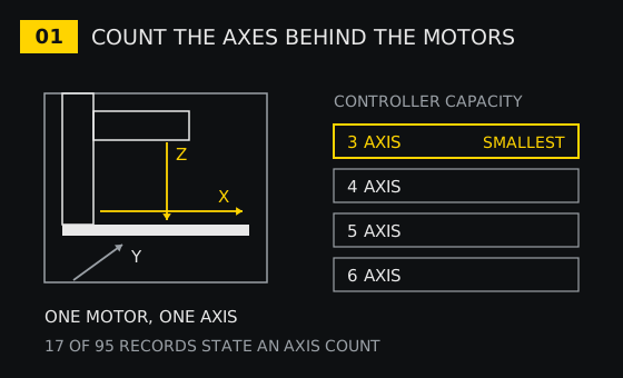
An axis is a motor that has to arrive at a position at the same time as the others. On a three-axis mill that is X, Y and Z. The spindle is a fourth motor, but it holds a speed rather than a position, so it is not an axis in the count. The tool changer is a sequence of relays and confirmations, so it is not an axis either. Counting the spindle or the changer as axes is how a buyer ends up with a 5-axis controller and no outputs left for the chuck.
Only 17 of the 95 records put a number in a dedicated field. Ten use Control Axis: 3-6Axis appears three times, 2/3/4/5/6Axis twice, and 2axis, 3axis 4axis 5axis, 1-6 Axis, 2 Axis Linkage and 2 Axis once each. Seven use Axis: 3axis five times, 3/4/6 axis once, 3-5Axis once. The other 78 records carry the count in the product name or not at all, which is why a name like EC500 USB Mach3 3/4/5/6 Axis tells you more than the specification table does.
Read the number as a ceiling, not a target. A 3-6 axis unit on a three-axis machine leaves two channels idle, and that is the correct way to buy if a fourth axis is a year away. A 2-axis control for a flame or plasma table, of which this category has several, cannot be stretched to a third axis by any setting: the channel is not there.
The output type is decided by the drives, not by the screen
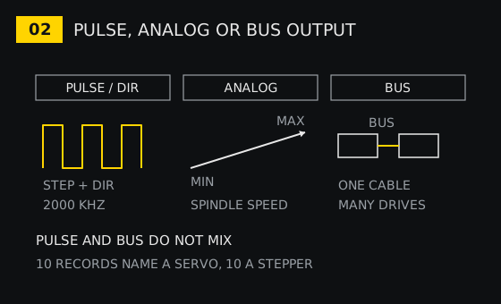
Three output families appear in these records. Pulse and direction is the one most retrofit buyers meet: the controller sends a train of pulses and a direction line to each drive, and the drive turns that into motor movement. The Mach4 USB breakout board quotes a pulse output speed of 2000KHZ; the 3/4Axis MKS3/4-V card quotes an isolated open collector output at 5V 20mA with the same 2000KHZ, and an isolation voltage of 3.5KV. Those are step and direction controllers, and they only talk to drives that expect steps.
Analog is the second family, and it is usually about the spindle rather than the axes. A spindle inverter wants a voltage that means a speed, and the controller needs a channel that can produce one that is stable. Bus is the third: the Lambda21E+PM95C+EX41A and NK280B stacks put the drives on a bus and the controller becomes a node on it, which is why those records are 15 kg cabinets rather than cards.
In this category, 10 records name a servo and 10 name a stepper, and the distinction is not cosmetic. One record describes a three-phase stepper driver, the 3DM580/3DM683, at 0.5-8.3A and 20-60VDC for NEMA23 and NEMA34 motors. If the existing drives look like that, the controller has to produce step and direction at a rate the driver can follow, and the current setting lives on the driver, not on the controller. If the existing drives take a voltage reference, a pulse controller will need converters, and converters are another box with another failure mode.
The only reliable way to settle it is to open the cabinet and read the drive terminals. PUL, DIR and ENA mean a pulse controller. A pair of wires to a potentiometer and a relay for run means the axis was never under numerical control, and the retrofit is a drive replacement, not a controller replacement.
The handwheel is an encoder with a dial on it
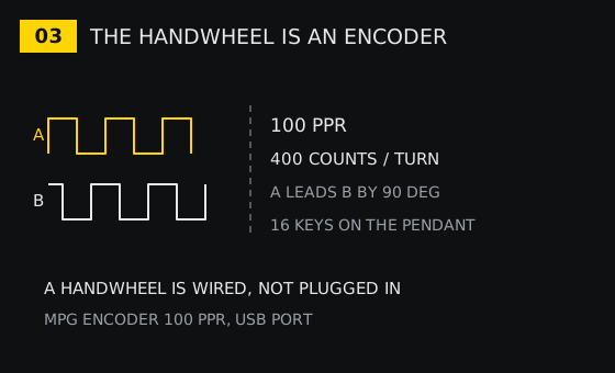
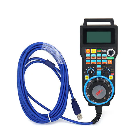
A manual pulse generator is not a knob the control reads as a position. It is a small encoder with a graduated dial on the front, and it produces two square waves, A and B, a quarter of a cycle apart. The controller counts the edges and looks at which channel changed first; that is how it knows the operator turned the wheel clockwise. One record in this category gives the number plainly: the LHB04B pendant carries an MPG Encoder of 100PPR and 16 keys, with a USB port and Mach3 as its system, in a plastic body.
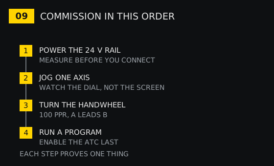
100 pulses per revolution, counted on both edges of both channels, is 400 counts for one turn of the wheel. That is the resolution the operator feels: at 400 counts per turn, one graduation on the dial is a small, definite step, and the jog is predictable. A pendant with a coarser encoder feels vague at the same feed, and an operator who does not trust the wheel stops using it.
The part that trips a retrofit is not the resolution but the protocol. The NVMPG pendant in this category is a 3/6 axis unit that talks over a serial line and has an LCD; the LHB04B is a wired pendant for Mach3 over USB; the WHB02 is a wireless handle for NC Studio; the WHB05P ships inside a PM95C+Lambda21A waterjet set; the F1510 is a wireless handle for the F2100B and F2300A plasma controls. None of those is interchangeable with the others. A pendant bought before the controller is a pendant in a drawer.
The port decides the cable, and the cable decides the PC
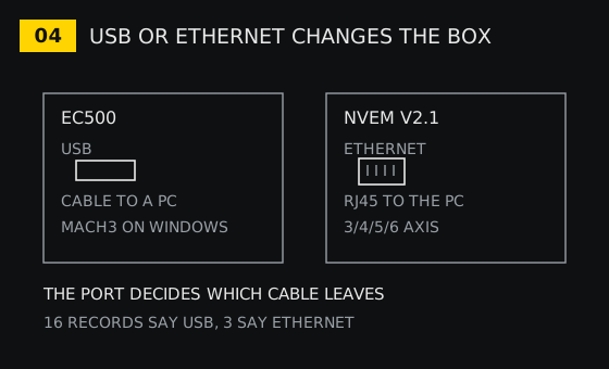
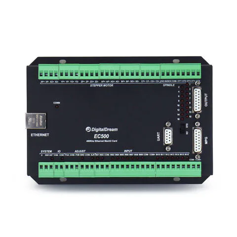
Sixteen records in this category mention USB and three mention Ethernet, and that ratio is a fair picture of the market. A USB controller is a card that turns a PC into a control: the EC500 is a USB Mach3 motion controller for 3/4/5/6 axes, and the XC809D is a 3-6 axis USB unit at 24V that runs FANUC-style G-code offline. Ethernet appears on the NVEM V2.1, a 3/4/5/6 axis card with an Ethernet interface for stepper and servo drives.
The distinction that matters in a shop is not speed. It is whether a computer becomes part of the machine. A USB card needs a PC that stays with the machine, a Windows install that is not updated by anyone, and a cable that survives the coolant. An offline control reads a file from a stick and runs it, and there is no operating system to break. For a retrofit in a workshop where no PC can live next to the machine, that is the whole decision.
The software side is a matching exercise of its own. One record for a vibrating knife controller lists supported systems from Windows XP through Windows 10 and a CAD package by name, which is unusually explicit; most records say only Mach3 or Mach4 in the title. A Mach3 card ties the machine to a Windows PC and to a motion plugin; an offline box ties it to a file format. Both are legitimate, and neither is a drop-in for the other.
The port also decides what happens on the day the control dies again. A USB card can be swapped in an hour if a spare is on the shelf. A bus system in a 15 kg cabinet with an expansion board cannot, and that risk belongs in the decision, not in the post-mortem.
Count the inputs before you fall for the axis count
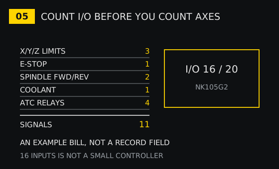
The NK105G2 record states its I/O as 16/20, which is sixteen inputs and twenty outputs, and that is a useful yardstick for a small router. Now write the bill for a three-axis mill: three limit switches, one e-stop circuit, two spindle directions, one coolant output, four relays for the tool changer. That is 11 signals, and it leaves five inputs and sixteen outputs on that board.
Five spare inputs sounds generous until the first upgrade. A probe needs one, a door interlock needs one, a pressure switch for the air blast needs one, a chip conveyor needs one and a second e-stop on the back of the machine needs one. The board that looked oversized at the quotation is the one that survives the second year.
The reverse is also worth saying. A 2-axis plasma or flame control has no tool changer outputs at all, because the process has no tool changer. Putting one on a mill means the ATC becomes a manual operation, and a machine that needs an operator to change a tool every cycle is a different machine from the one that was quoted.
24 volts at the terminals, 5 volts inside the ribbon
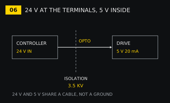
The cabinet has two electrical worlds. The control side runs on 24V: the XC809D is listed at 24V, the XC609 stand-alone control at DC24V, and the TC-6832 knife controller at DC24V 3A. The drive side is logic level: the MKS3/4-V card quotes 5V 20mA on an open collector output, and the same record quotes an isolation voltage of 3.5KV between that output and the control side. The Mach4 breakout accepts 6-24V on its inputs precisely because it expects the cabinet to be a 24V world.
The isolation rating is not a marketing number. It is the reason a shorted limit cable on the 24V side does not take the motion chip with it. It also means the two sides must not share a ground: bonding them at the terminal strip defeats the barrier and turns a cheap repair into a dead board.
The voltage field will not save you here. 79 of the 95 records leave Voltage blank, and ten more say other or OTHER in one casing or another. The label on the existing supply and the markings on the drive terminals are the only reliable sources, and they are worth photographing before anything is disconnected.
The parameters the old machine already owns
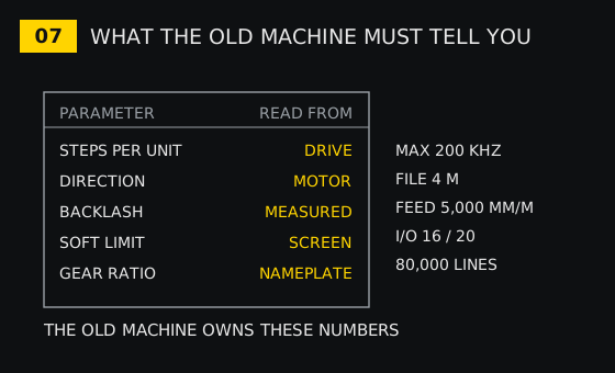
A controller is a computer that has been told how big the machine is. Five of those statements have to be recovered from the old control or measured on the machine: steps per unit, axis direction, backlash, soft limits and the gear ratio between motor and screw. Each has a different home. Steps per unit lives in the drive microstep setting or in the old parameter page; direction lives in the motor wiring or in a sign in the parameters; backlash is measured with a dial, not read; soft limits come off the old screen; the gear ratio comes off the pulley or the nameplate.
The new control also arrives with its own ceilings, and they decide whether the old programs still run. One 2-axis plasma control in this category quotes a maximum of 200 kHz on its pulses, 80,000 lines of code, a 4M single file and 5,000 mm/m of feed. An NK105G2 quotes an ARM11 CPU, 256M of flash, an I/O of 16/20 and a 128 by 64 LCD module. An M350 offers a 7 or 10.2 inch display. A file larger than 4M does not fit, a feed above 5,000 mm/m is not reachable, and a program past 80,000 lines stops at the line where the buffer ends.
The same card is the reason a retrofit can be quoted honestly. With the five values in hand, the axis count and the output type, the remaining unknowns are the handwheel protocol and the I/O margin, and both are visible on the bench.
What these 95 records can and cannot tell you
The category is broad, and the coverage is uneven in a way that is worth knowing before reading a record as a specification. 62 of the 95 list Milling Machine as the application, 15 leave it blank, three say Lathe and Turning Center, and the rest are waterjet, woodworking, PLC or none. Only 17 carry an axis count in a field. 85 leave Control Axis blank. 79 leave Voltage blank. 61 say the memory is none. 28 records weigh 1 kg, 14 weigh 1.5 kg and 13 weigh 0.5 kg, and the heaviest is 16 kg.
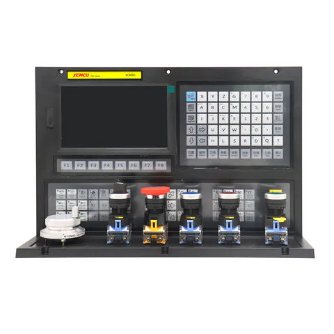
Weight is the most honest field in the table. One kilogram is a card in an antistatic bag. Fifteen kilograms is a cabinet with a bus system, an expansion board and a power supply, and it will not fit in the space the old control occupied. If the retrofit has a fixed envelope inside the cabinet, that number decides before any other.
The panel in the photograph is the other half of the decision, and it is the half that records describe badly. An e-stop, a membrane keypad, a row of function keys and a small handwheel are not controller features; they are the surface the operator touches forty times an hour. A retrofit that gets the axis count and the output type right and leaves the operator with a mouse and a keyboard has moved the difficulty rather than removed it.
The spindle and the tool changer are not axes
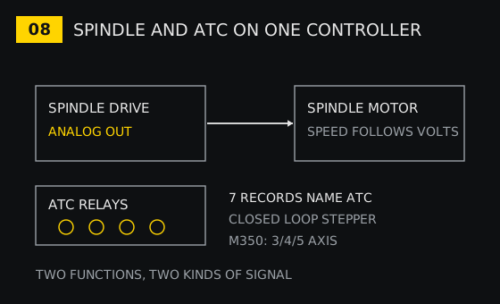
The spindle takes a speed reference and returns a confirmation; the tool changer takes a sequence of outputs and returns a set of confirmations. Seven records in this category name a tool changer, and one of them, the M350, pairs closed loop stepper support with ATC handling across 3, 4 or 5 axes. That pairing is the point: a control that can interpolate five axes and has no changer logic gives a machine with a very accurate spindle and a manual drawbar.
If the retrofit keeps the changer, the output count has to include it, the ladder has to exist in the control and the confirmations have to be wired to inputs that the control can read at the speed the changer moves. If it does not keep the changer, that decision should be made before the controller is ordered, because a control bought for a manual machine cannot grow the function later without a different control.
The order to check a retrofit in
- Read the cabinet before buying: drive terminals, supply voltage, limit wiring, changer relays, and the five parameters from the old screen. Photograph every terminal strip.
- Match the axis count to the motors that must interpolate, then check the I/O bill against the board. Add the changer and the probe on paper, not after the invoice.
- Match the output type to the drives. Pulse and direction, analog or bus, decided by what is already bolted down, and by nothing else.
- Match the handwheel to the control family. The pendant protocol is not universal, and a pendant bought early is a pendant unused.
- Commission in one direction only: 24V rail measured, one axis jogged against a dial, the handwheel checked for direction, then a program, then the changer. Each step is a proof, and a failure at step two is cheaper than a failure at step five.
A retrofit that follows that order ends with a machine that runs the old programs on the old drives, which is the only definition of success that matters. A retrofit that starts from a controller somebody recommended ends with a cabinet full of adapters and a handwheel in a drawer.
Related reading and the parts named here
The controller category lists the records behind every number on this page. The A2 guide covers the order to check a machine once it stops repeating, which is the step after a retrofit runs its first part. The A8 guide covers what a probe can and cannot prove about the geometry the new control now commands, and the A10 guide covers how to read a record as a record rather than as a promise. If the machine also needs its table reworked, slide tables covers the stroke and lead numbers that decide the travel the controller is allowed to command.
Records cited above include the EC500 USB Mach3 card for 3/4/5/6 axes, the XC809D 3-6 axis USB control at 24V, the LHB04B wired pendant with a 100PPR encoder and 16 keys, the NVMPG 3/6 axis pendant with its serial line, the M350 3/4/5 axis control with closed loop stepper and ATC support, the Mach4 USB breakout at 2000KHZ, the MKS3/4-V card at 5V 20mA, the 3DM580/3DM683 three-phase stepper driver at 0.5-8.3A and 20-60VDC, the NK105G2 with its 16/20 I/O, and the F2300A with its 200 kHz, 80,000 line, 4M and 5,000 mm/m limits. Send the drive terminals, the supply voltage and the five parameters before ordering, and the match can be checked on paper in an afternoon rather than in the cabinet over a week.