Machine accuracy has dropped: the order to check things in
This page is about the order to work in when a machine that used to hold size stops holding size. For the parts themselves — scales, probes, lining — the category links are at the end.
Why the order matters
The feedback chain reports where the axis is. It cannot report where the work sits against the tool. If the ways have worn so that the slide lifts or yaws as it traverses, a scale mounted on that slide still reports its own travel accurately — while the cut moves. The readout can be right and the part can still be wrong.
That is the whole argument for the order below. Faults further down the chain are the ones people reach for first, because they are easier to see and easier to replace. Fitting a new scale to a machine with worn ways does not correct the machine: the new scale reports the same motion, in finer increments.
There is a second reason, and it is about cost. Each stage in the order is more expensive to act on than the one before it, and the later stages are the ones that need new parts. Ruling out the cheap mechanical explanations first is what stops money going into the control side for a fault that lives in the iron.
Stage 1 — Geometry: is the machine still moving straight?
Start with the machine itself, because every reading taken later inherits whatever error is here. What you are establishing is whether each axis still travels straight in the horizontal and vertical planes, whether the axes are still square to each other, and whether the machine holds those relationships once it is warm.
- Straightness of travel. An indicator on the moving member, read along the full travel, shows a slope or a step where the way has worn. The reading is usually worst where the machine works most.
- Squareness between axes. A square or a test bar against each axis in turn. A machine out of square makes parts consistently wrong in one direction — which is often mistaken for a programming problem.
- Parallelism and level. Worth re-checking before anything else: it is quick, and it is where a machine that has been moved or re-shimmed usually starts.
- Repeatability after warm-up. Take the same reading cold and again with the machine running. If the two differ you are looking at thermal behaviour rather than wear, and the two need different answers.
Two signatures are worth separating at this stage. An error that repeats at the same place on every traverse, on every part, points at the geometry. An error that appears only once the machine is warm, or only while it is cutting, points at thermal growth or at a slide that is not held firmly — and it will not be cured by anything you adjust further down the chain.
Stage 2 — The way lining, if the slide runs on one
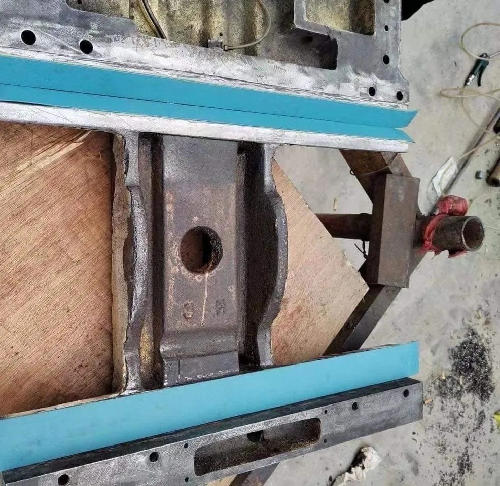
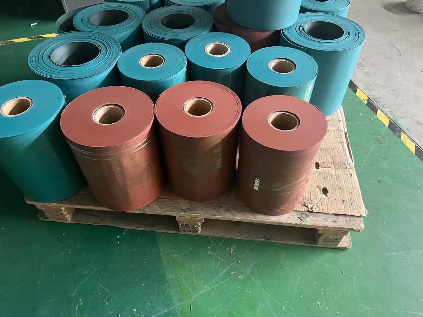
Many slides carry a bonded low-friction lining running against a lubricated cast-iron way — a PTFE-based material of the Turcite B type. It is there to wear, and to wear instead of the iron. That makes it the first suspect once the geometry has been shown to move, and the last thing anyone wants to strip if it is not the cause.
The signals that the lining is the cause, rather than a symptom of something else:
- It moves in steps when it creeps. Stick-slip at low feed, chatter marks on the finished surface, and a slide that feels like it is gripping and releasing.
- The error appears the moment the axis reverses. Lost motion on reversal is the classic sign that the bearing surface can no longer hold a consistent film.
- It is worst where the slide lives. Compare the error map along the travel against where the slide spends most of its time; wear concentrates there.
- The mating iron shows it. Scoring, smearing, picked-up metal or bright polished patches on the cast-iron way. Damage in the iron matters as much as wear in the lining, because a new lining will not restore geometry onto a damaged way.
- The oil no longer stays put. Choked or polished-out oil grooves. Operators describe it as running dry even though the lubrication system is working.
Stage 3 — Feedback: the scales that report the travel
Only once the machine has been shown to move straight is it worth asking whether it reports that movement correctly. A fault here is usually recognisable by its pattern rather than its size.
- An error that grows steadily along the travel. Points at the scale, its mounting or its alignment rather than at the machine: a scale that has shifted on its mount reports a slightly different distance for every millimetre of real travel.
- An error that appears only at speed. A read head working at the edge of its gap, or dirt on the scale face, shows up during rapid traverse and disappears when you creep.
- Jumps, drops or alarms. Contamination on the scale face, coolant ingress, a wiper that has stopped wiping, cabling or earthing. A scale is an optical device living in a coolant-rich environment; the sealing and the wiper are doing real work.
- A reading that is right and a part that is wrong. This is not a scale fault. It is Stage 1 again — the scale is faithfully reporting an axis that is not moving straight.
What to look at with the covers off: whether the read head is still seated where it was set, whether the scale face carries any film or swarf, whether the wiper is intact, and how the cable is routed and strain-relieved. A cable that flexes on every traverse eventually changes what the machine reports.
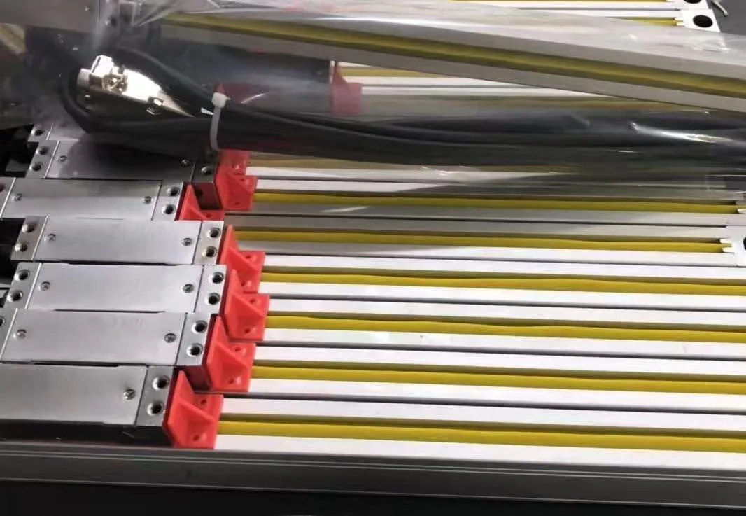
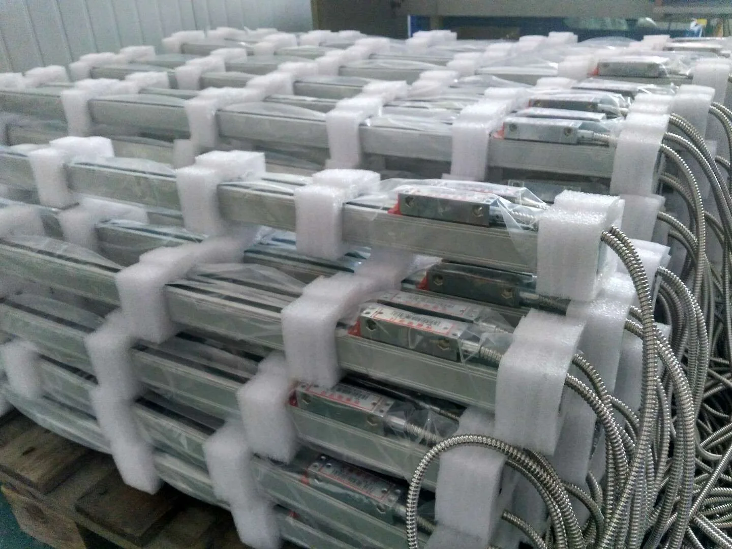
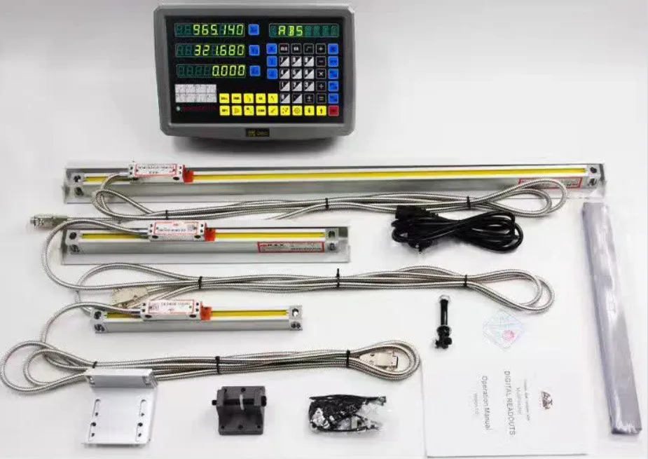
The figures published on the listings in the Linear Encoder category are useful as a baseline, not as a promise. The incremental families listed there (SGC-2, SGC-4.2, SGC-5, SGC-6, SGC-7, SGC-8, ZFF-30A, ZCF-1) and the absolute families (JFT-10, JFT-40) each carry their own measuring length and accuracy: JFT-40 is listed with an accuracy grade of 3 µm / 5 µm, SGC-4.2 with a 100–6200 mm length range, and JFT-10 with a stated resolution of 2.5 nm and BiSS/SSI output. Those figures describe the scale. Whether the machine holds them is Stage 1.
Stage 4 — Probing: where the datum comes from
The probe is the last link and the one that decides where the part is. A fault here is deceptive because it is consistent: every part made from that setup is out by the same amount, which looks exactly like a machine that has lost accuracy.
- Re-seat the probe and repeat the measurement. If the result changes, the holder, the taper or the mounting is at fault — not the machine.
- Look at the stylus. Bent, cracked, loose at the tip, or worn flat. A stylus is a consumable and behaves like one.
- Check the cable and the connector. On a wired probe, strain and seating. On a wireless one, the battery and the optical path — especially with coolant mist on the windows.
- Re-establish the calibration after any change. Probe offsets describe one stylus on one holder. Change either and the offsets are describing the old one.
- Measure something you already know. A check against a known feature separates "the machine has moved" from "the datum has moved".
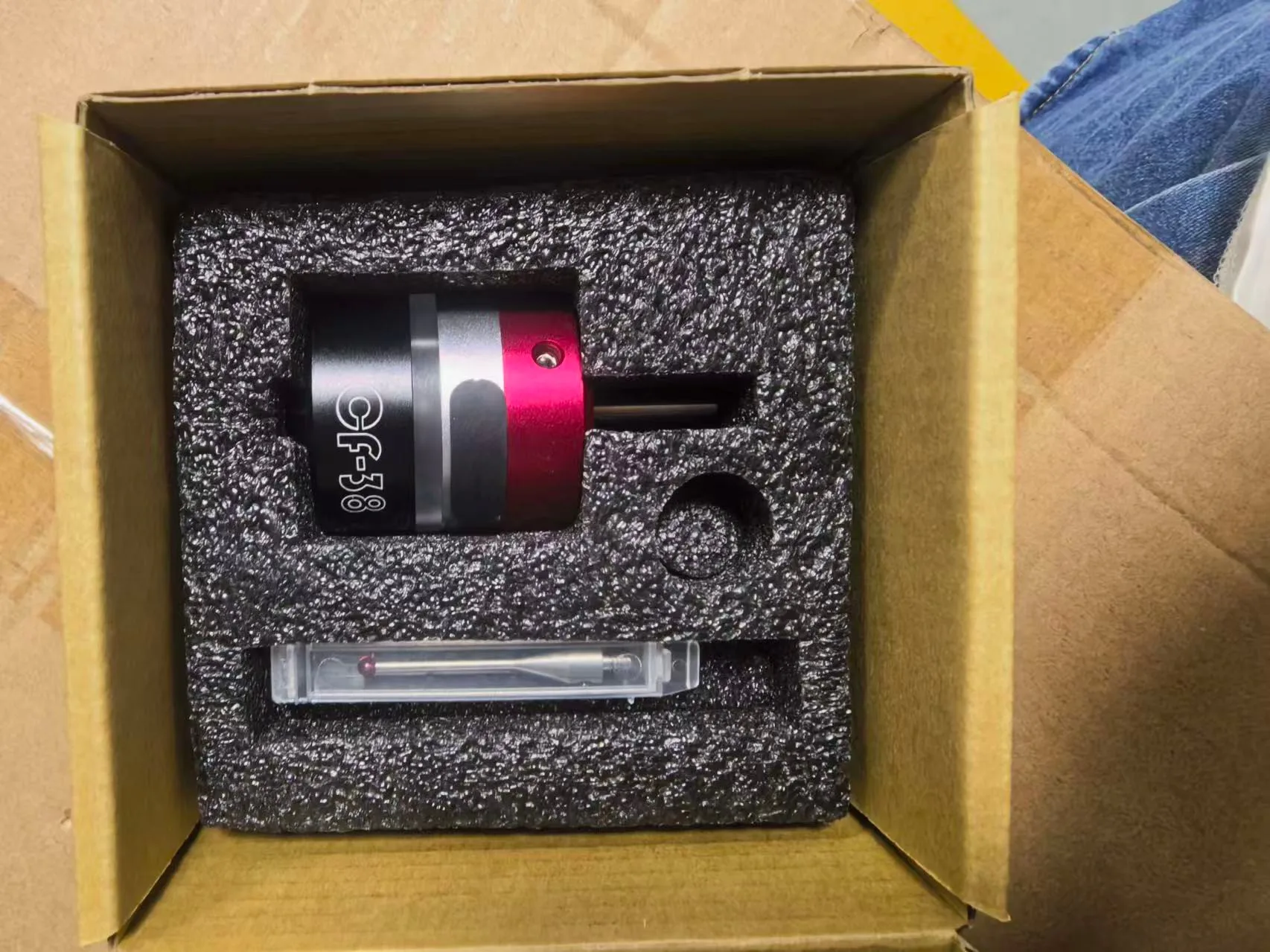
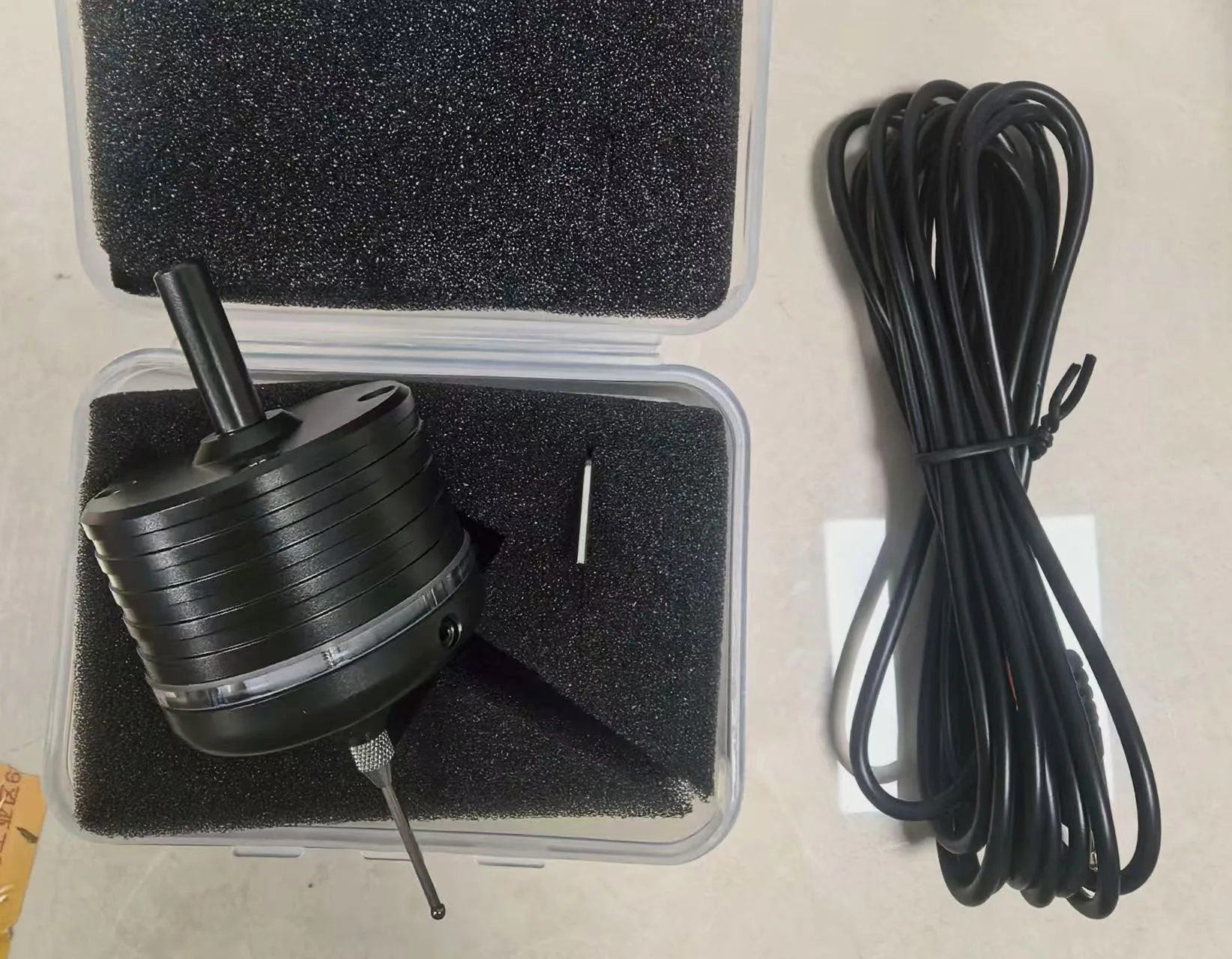
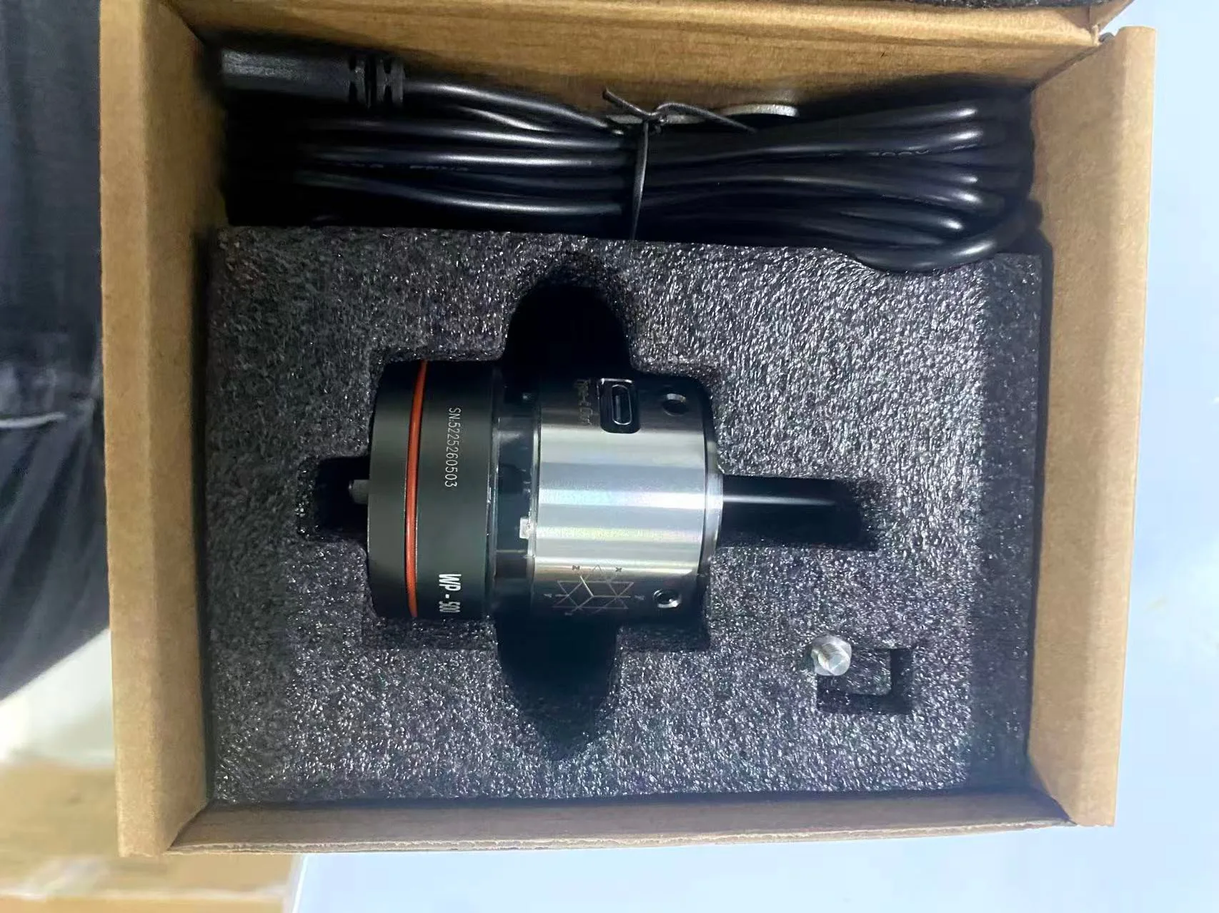
The Touch Probe category lists the families in more detail: the wireless machining-centre probes (MDP40, GP-800), the infrared T40, the manual and optical edge finders, the wired contact probes such as the T-25, the CF-38 3D edge finder, and the Z-axis tool setters. Which one belongs on a given machine is a mounting-and-signal question rather than a diagnostic one; for this page, what matters is that the probe is calibrated for the stylus actually fitted to it.
The order, in one view
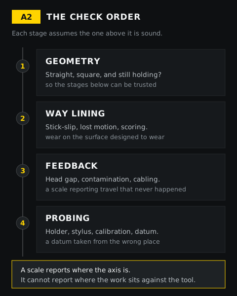
The dependency runs one way. Each stage assumes the one above it is sound, and a reading taken below a fault is a reading you cannot use.
If you only have five minutes
Five questions, answered from the machine and the paperwork, usually tell you which stage to open at:
- Did the error appear at the same time as a change — a new tool, a new fixture, a changed offset, a software update, a different operator? If yes, start at Stage 4.
- Does the error repeat at the same point on every part? If yes, it is repeatable, and the geometry or the scale can be repaired or compensated. If no, look for something loose or thermal first.
- Does it change between a cold machine and a warm one? Then the machine is moving with temperature, and no amount of probe calibration will hold it.
- Does it appear only under load? Then look at the slide and the clamping, not the scale.
- Is the finished surface marked — chatter, steps, a pattern that repeats with the axis? Then start at Stage 2.
Where to go next
The parts referred to above: Linear Encoder, Touch Probe and Turcite B. If the lining turns out to be the cause, the relining guide covers the decision and the nine steps of the job. And if you would rather describe the fault than read about it, tell us what the machine is doing — the measurement record from the note above is the useful thing to send.