A touch probe that repeats to 0.001 mm can still measure the wrong size
A probe record quotes one number, and it is usually read as a promise about the part. This page separates what that number covers from what it leaves to you. For where runout comes from once the probe is trusted, see the collet and holder guide.
Three words that get used as one
A probe record says 0.001 mm and the figure starts travelling: into quotations, into fixture arguments, into the claim that a machine can hold a size. It is a real figure, measured on a real instrument, and it means one narrow thing. It does not mean the machine knows where your part is.
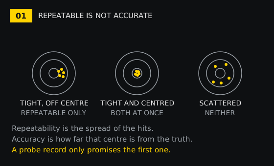
Repeatability is the spread of repeated hits at one point, from one direction, with one stylus. Accuracy is how far the centre of that spread sits from the true position. Calibration is the bridge between them, and it is the only one of the three that you control on the shop floor.
What 0.001 mm is measured on
The figure comes out of a controlled loop. The probe is mounted, a stylus is fitted, the machine touches one point on a reference many times, and the scatter of the returned coordinates is recorded. Nothing in that loop involves your workpiece, your fixture or your warm-up routine.
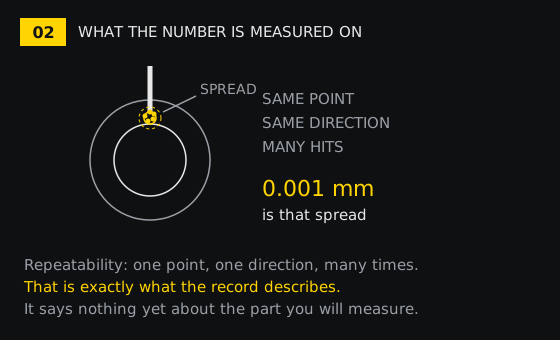
So the number answers a precise question: if I touch this same point again, how far will the answer move? It does not answer whether the point is where the model says it is, and it does not answer whether the stylus is the one that was calibrated.
The signal does not fire where the ball touches
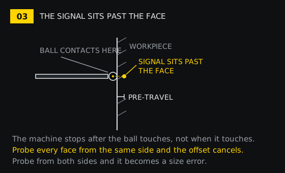
The ball touches the surface, the stylus deflects, and only then does the switch inside the body trip. The coordinate the machine keeps is the body position at the trip, which lies a little past the surface, inside the material.
Because the deflection happens along the direction of travel, the offset has a direction. Probe one face from the left and the opposite face from the right, and the two readings no longer agree; on a width, that disagreement appears as a size error that no amount of re-zeroing removes.
Stylus length is a lever
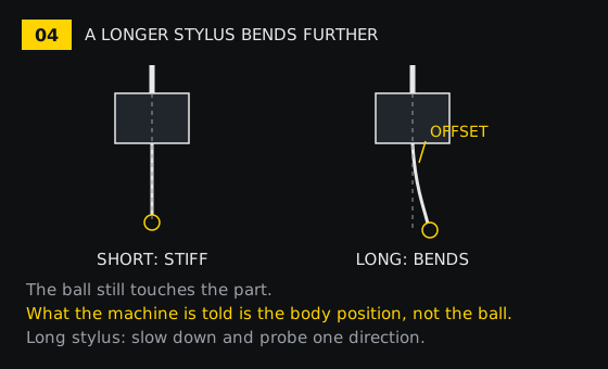
A long stylus reaches deeper into a bore or past a fixture, and bends further for the same contact force. The ball still touches the part. What the machine is told is where the probe body sits, and the body sits at the end of a lever that has just been loaded.
Two practical consequences. Long styli want slower probing feeds and a single approach direction, so the bend is at least repeatable. And changing a stylus invalidates the calibration, because both the length and the bend have changed.
The part moves under the ball
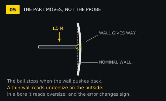
Records in this category list the contact force as 1.5 N. That is small, until the feature being measured is a thin wall, a tube or a slot with one open side. Then the wall bows away under the ball and the ball follows it.
The sign of the error depends on the side you probe. Approaching a wall from outside reads undersize because the wall moves away; approaching the far side of a bore reads oversize for the same reason. The part is not wrong. The measurement is loaded.
Five millimetres of travel, then the body moves
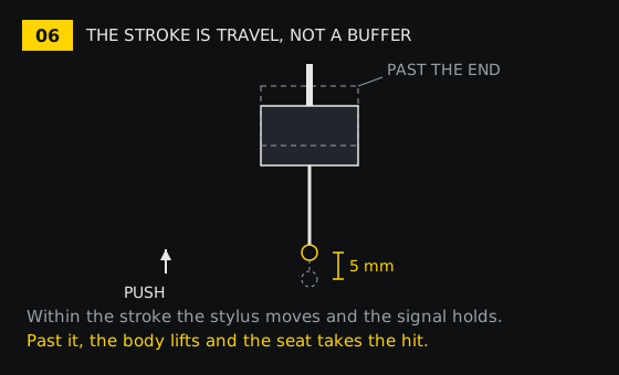
The same records list a stroke of 5 mm. That is overtravel: the distance the stylus can be pushed before something else in the assembly takes the load. It exists so that a cautious approach does not damage the probe, not so that the machine can approach faster.
Past the end of the stroke the stylus cannot move further, so the body lifts, the seat separates and the load lands on parts that were never meant to carry it. After that the probe may still repeat perfectly, against a zero that has moved.
Three points hold the zero
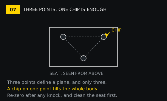
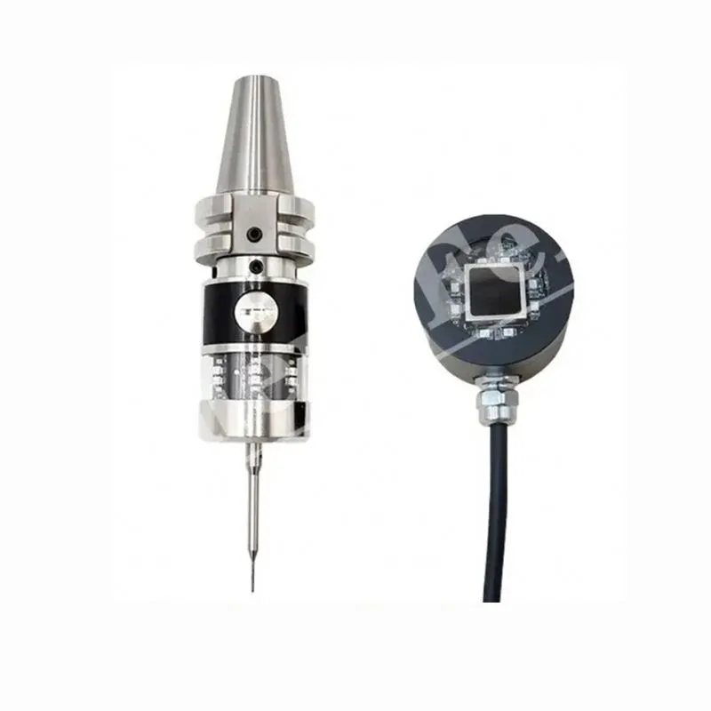
Inside the body the stylus assembly rests on a kinematic seat: three points that define one plane and one position. That is what makes a probe repeat. It is also what makes it fragile, because three points have no redundancy.
A chip, a film of dried coolant or a burr on one point tilts the whole assembly, and it tilts it differently every time the probe is knocked and reseated. The scatter can still look healthy while the zero walks.
Calibration is where the number becomes usable
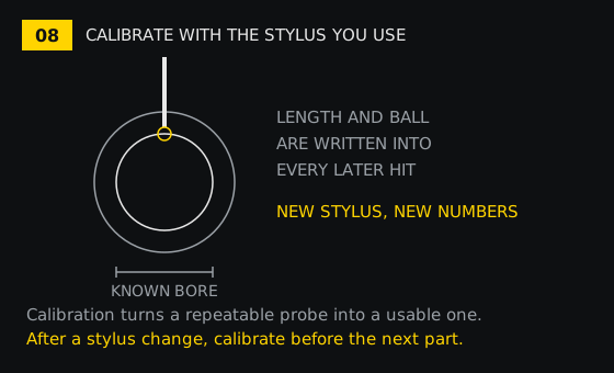
Calibration touches a known bore or a datum sphere, compares what the machine reports with what the artefact actually is, and stores the difference along with the stylus length and ball radius. From then on every reading is corrected by those stored values.
That is why calibration belongs to the stylus, not to the probe. Fit a different stylus, or knock the one you have, and the stored values describe a probe that no longer exists.
What the records in this category actually say
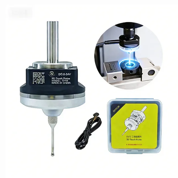
The records list what a buyer can check: repeatability 0.001 mm, stroke 5 mm, contact force 1.5 N, protection to IP67, height 62 mm, bottom diameter 54.5 mm, weights from 0.2 kg to 3 kg, and an electrical life quoted as 3000000 times.
What they do not list matters as much. There is no accuracy figure, no statement of which stylus the repeatability belongs to, and no calibration artefact named. Those are the questions to ask before an order, because they decide whether the 0.001 mm applies to your setup.
Six checks before you blame the probe
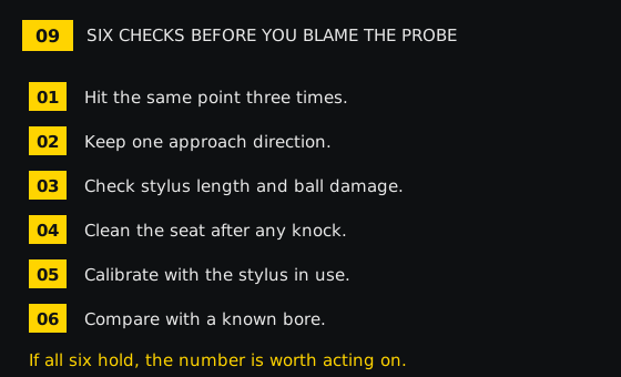
- Hit the same point three times and look at the spread before trusting one hit.
- Probe every face from the same direction, so the pre-travel offset cancels instead of adding.
- Check the stylus: length as calibrated, ball free of build-up, shaft not bent.
- Clean the seat after any knock, and re-zero rather than assuming it survived.
- Calibrate with the stylus that is in the machine, on the artefact you will use.
- Compare the result with a known bore, not with the model, before cutting the part.
None of that is a repair. It is the difference between a number the machine produced and a measurement you can act on, and it takes less time than the first scrapped part.
Related reading and the parts named here
The collet and holder guide covers the other half of the same problem: once the probe is trusted, where runout enters the cut. The touch probe category lists the records behind this page.
Named above: the V6 3D touch probe, the GP-800 wireless probe and the MDP40 wireless probe. Send the stylus length and the feature you need to measure and we will confirm what the figure covers.