The vise lifts the workpiece: reading jaw parallelism before the first cut
The vise takes the blame for lift because it is the part that moves. But a vise can only lift a workpiece if one of its jaw faces is not where the drawing says it is, and a dial indicator will say which face is wrong before anything is spent.
The part is not pushed down, it is levered up
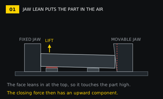
A machine vise closes horizontally. Nothing in the mechanism presses a workpiece down onto its parallels; the part stays seated on its own weight and on friction at the two jaw faces. When a jaw face is not vertical, the closing force is not horizontal either. The part of that force which points up is small, but it acts on a part weighing a few kilograms and is resisted only by friction, so it wins.
The symptom always has the same shape: the part sits flat, the vise closes, and the end furthest from the movable jaw rises. How far it rises depends on two things, how far the face is out of vertical and how high the contact sits above the seating face. It does not depend much on how hard the vise is tightened. Tightening harder usually makes the lift worse.
Clear the seat first
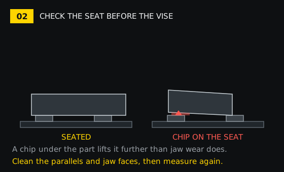
A chip, a burr or a dried film of coolant under one parallel produces the same reading as a worn jaw, and it takes a minute to rule out. Wipe the parallels, both jaw faces and the underside of the part. Run a fingertip along the top face of each parallel. Anything you can feel is larger than the error you are chasing, because the figures in the catalog are stated in hundredths of a millimetre.
- Parallels. Same pair, same height, no burr on the top face, both seated on a clean bed.
- Jaw faces. No chip welded to the face. A chip embeds in soft material and survives a wipe.
- The part. A burr on the face that sits on the parallels tilts the part before the vise touches it.
If the part still lifts after that, the error is in the vise or in the part, and the next three checks separate them.
Put the indicator on the part
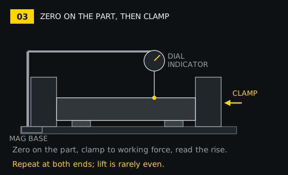
Mount the indicator on a magnetic base on the vise body or on the table, never on the movable jaw. Touch the stylus to the top face of the workpiece, directly over one of the parallels, and zero the dial. Close the vise to the force you actually use in production, then read the needle without leaning on anything.
- Zero on the top face at the end nearest the fixed jaw.
- Clamp to working force and read the rise.
- Release, move the stylus to the other end, zero and repeat.
- Turn the part over and repeat once, to separate a burr from a bent part.
Three faults, three readings
Lift in a plain vise has three common causes, and each one leaves a different fingerprint on the indicator. The order below runs from the cheapest fault to confirm to the most expensive.
The fixed jaw face is not vertical
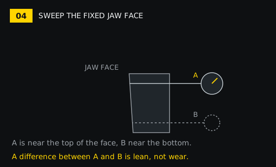
Sweep the fixed jaw face with the vise open and nothing clamped. Read the face near the top, then near the bottom. If the two readings agree, the face is vertical. If they differ, the face is leaning, and the direction of the lean says which end of the part will rise. Wear leaves a different signature: a hollow in the middle of the face, or a rounded top edge where parts have been sliding in and out for years. A hollow reads low in the middle and high at both ends; a lean reads a steady difference from one end to the other.
A leaning jaw can sometimes be corrected by grinding. A jaw that is hollow in the middle usually cannot, because grinding it flat again removes more hardened material than the jaw can spare.
The movable jaw tilts under load
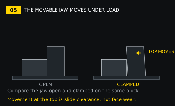
The movable jaw slides on the body and is pushed by the screw. Clearance in that slide lets the jaw rotate a little when the screw loads it, so a face that was vertical at rest is no longer vertical under clamping force. Measure the jaw body with the vise open, clamp a block to working force, and measure the same place again. Movement at the top of the jaw under load is slide clearance, not wear.
This fault is easy to mistake for wear because the symptom on the part is identical. The difference is that a tilting jaw moves and a worn jaw does not. If the jaw moves, grinding the face corrects the shape of the face and leaves the movement in place.
The part is not square
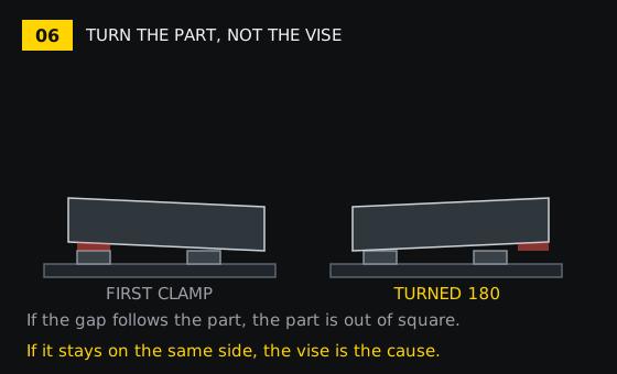
Clamp the part, note which end lifts, release it, turn it 180 degrees about the vertical axis, and clamp it again in the same place on the jaws. If the lift follows the part, the part is the problem: one face is not square to the face that sits on the parallels, or the two faces are not parallel. If the lift stays on the same side of the vise, the vise is the problem.
This is the check that decides whether to work on the vise at all. A part that is out of square will lift in any vise, and no amount of grinding will change the reading.
Read parallelism as a rate
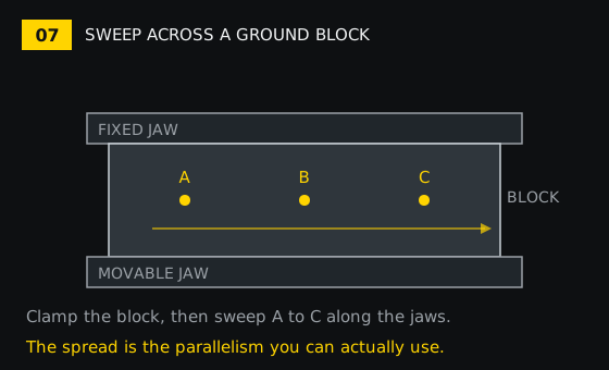
Jaw parallelism in the catalog is stated over a length. The GT-series records state 0.005 mm over 100 mm. Other records in the same category state 0.02 mm over 100 mm. That is a rate, not a single number: the permitted spread grows with the length you measure over, so a reading taken across a longer jaw is compared with the rate rather than with the absolute figure.
Squareness is stated separately, at 0.005 mm on the records that carry both figures. Parallelism and squareness are different errors. Parallelism compares the two jaw faces with each other and with the bed. Squareness compares a jaw face with the side of the body. A vise can be parallel and still out of square, and a part clamped against the side stop inherits that error.
- 0.005 mm over 100 mm on the GT-series records, with squareness at 0.005 mm on the same records.
- 0.02 mm over 100 mm on a second group of records. A different class of vise, and a different cost when the job needs the tighter one.
- 0.01 mm on a record that combines parallelism and squareness runout in a single field.
What the record says about the jaw
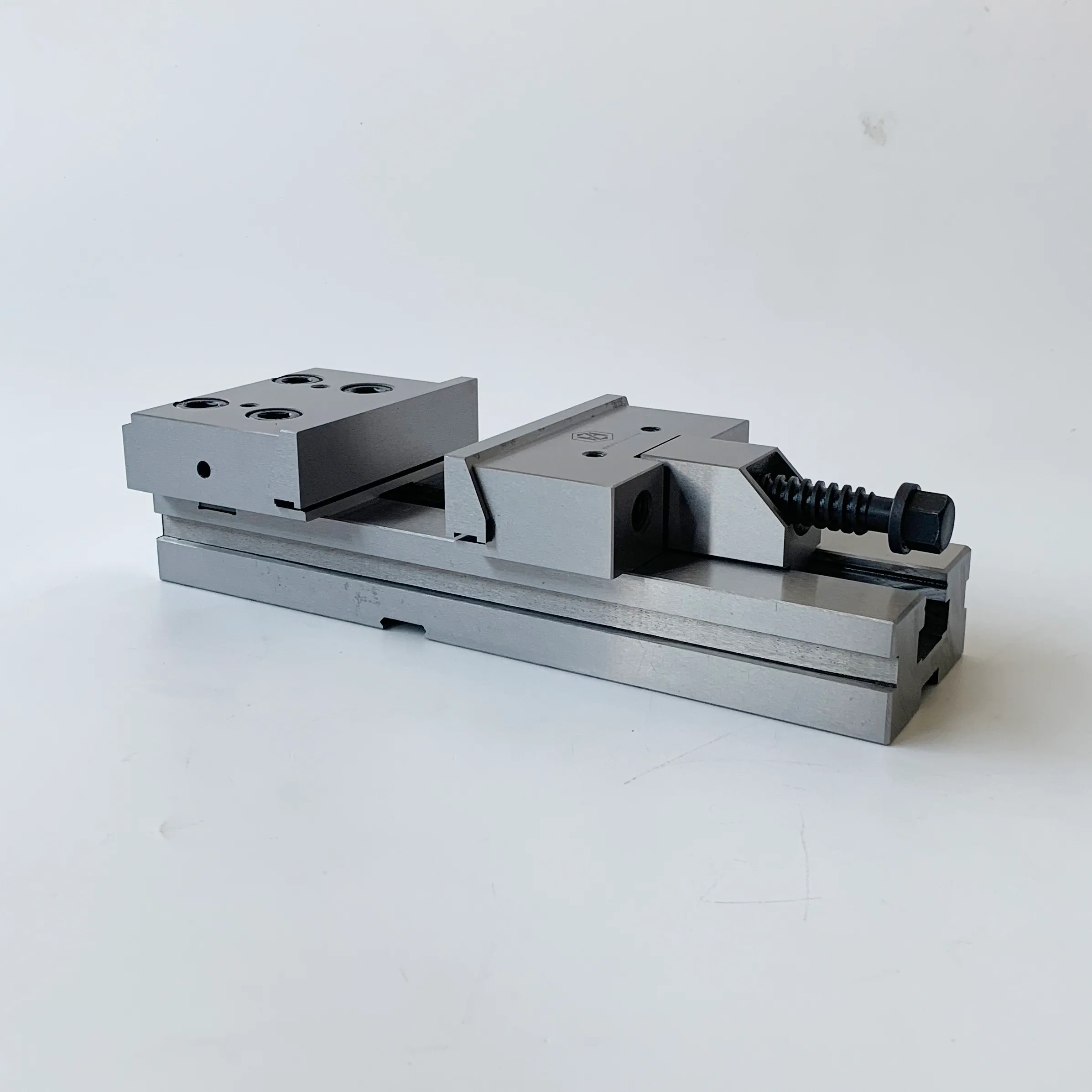
The records that state the parallelism also state what the jaw is made of and how hard it is: 20CrMnTi on the GT-series records, hardened to HRC58~62. That hardness is why a jaw can be reground once and not twice. It is also why a jaw ground through its hardened layer will not hold a reading for long, however carefully it was set up.
Size and clamping range come from the same place. The records list jaw widths of 50 mm and 60 mm on the smaller angle vises, clamping ranges of 0-200 mm, 0-60 mm and 0-45/0-60 mm depending on the model, and a clamping force of 3000 Kg on one of the precision records. Those figures describe what the vise can hold. They do not describe what it can hold square, which is the subject of this page.
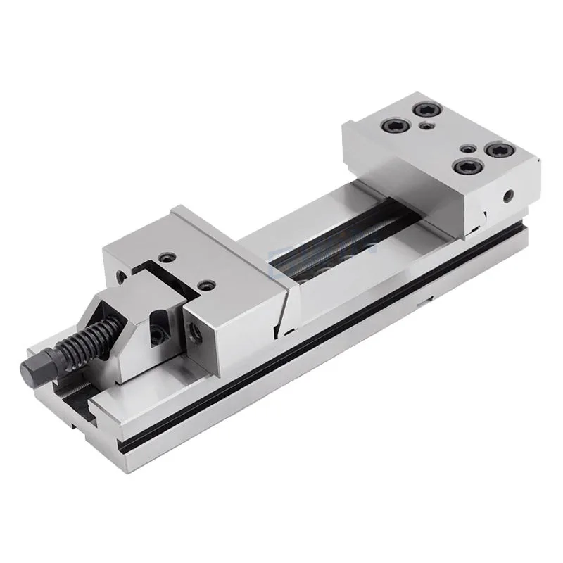
Model families in the catalog are GT100 / GT150 / GT200, GT150A x 200, QKG25 / QKG38 / QKG50 and QGG88. The family tells you which jaw and which spare parts fit. It does not tell you the condition of the vise in front of you. That is what the indicator is for.
What grinding can and cannot do
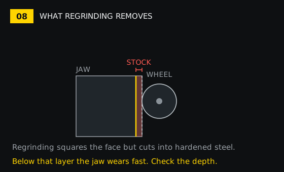
Grinding the jaws in place is the standard repair for a face that is leaning or lightly worn. The jaws are clamped or preloaded the way they are used, the faces are ground together, and the reading comes back. What grinding cannot do is restore material that is not there. Every pass removes hardened stock from a jaw that was hardened to HRC58~62 for a reason.
Two limits decide the outcome. The first is depth: once the wheel is past the hardened layer, the face is soft and will wear into a hollow quickly. The second is geometry: grinding the faces changes the jaw height and the position of any step or stop face, so a jaw with a machined step may need to be replaced rather than ground.
Repair or replace
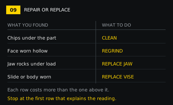
The decision follows the reading, not the calendar. Work down the list and stop at the first line that explains what the indicator showed.
- Chips and burrs. Clean. No repair and no parts.
- A leaning or lightly worn face, with the rest of the vise sound. Regrind, if the hardened layer allows it.
- A jaw that moves under load, or a face worn hollow past grinding. Replace the jaw pair, not one jaw. The pair is matched, and a single new jaw against a worn one holds the part at an angle.
- A slide that rocks with the jaws closed on a block, or a body worn at the sliding fit. Replace the vise. Regrinding a jaw on a body that moves will not hold a reading for long.
What to send us
If the reading is ambiguous, send the numbers rather than a description: where the stylus sat, the reading before and after clamping, and the model or the jaw width. A photograph of the jaw faces taken straight on, with light raking across them, often shows a hollow that a photograph taken at an angle hides.
Related checks: turcite B guideway relining when the error is in the machine rather than in the vise, machine accuracy loss for the order to work in when several things are wrong at once, collet holder runout for the tool side of the same problem, and chuck and live centre concentricity for the turning equivalent.
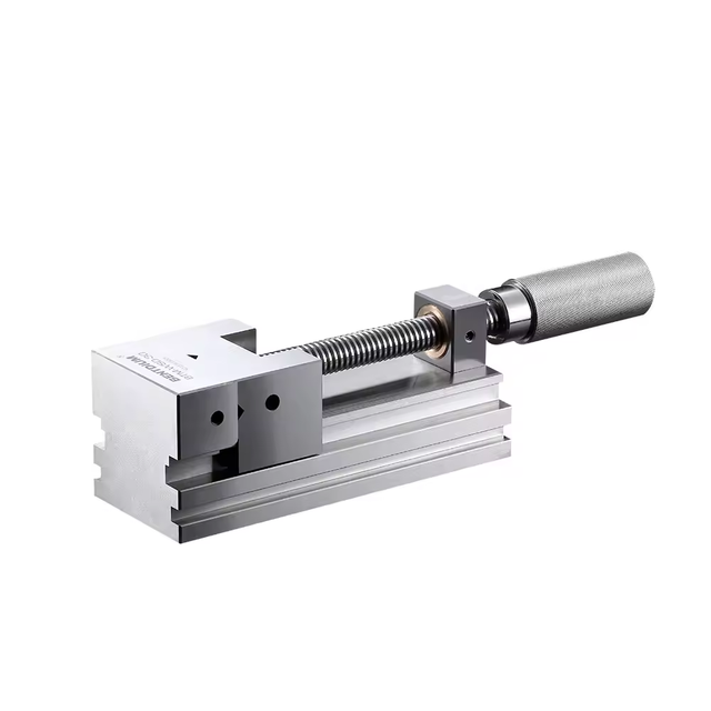
Parts cited above: the GT150 / GT175 / GT200 modular vise, the QKG38 / QKG50 precision vise and the QGG / QKG / GT milling vise. The plain vise category lists the rest by model. If the model is not there, send the jaw width and the clamping range and we will match the family. Contact us with the readings.