Turcite B replacement: how to tell a machine-tool guideway needs relining
This page is about the decision: whether a sliding guideway has worn past the point where adjustment and lubrication still help. For the material itself — colours, sheet widths, thicknesses and adhesive — see the Turcite B category.
Why sliding guideways lose accuracy
A sliding (box) guideway carries the moving member on a low-friction lining bonded to one face. On a great many machines still in service that lining is a PTFE-based material of the Turcite B type: bonded to the moving surface, then machined and scraped back to geometry.
The lining is there to take the wear instead of the iron. It runs against a lubricated cast-iron way, keeps friction low, and resists the coolants and lubricating oils that are always present on a machine tool. Wear is therefore expected. The question is not whether the lining has worn, but whether it has worn past the point where anything short of replacement will bring the machine back to geometry.
The signals that the lining is done
- Geometry stops holding. You level and align the machine, and within days or weeks it drifts out again. A little movement after a fresh alignment is normal settling; repeated drift usually means the bearing surface can no longer hold a consistent oil film.
- Unexplained taper in turned work. Same program, same tool, same material — and the taper along the bed grows. It is one of the first things an operator notices and one of the last things anyone suspects of being a guideway problem.
- Rock or walk as the axis traverses. The slide lifts or drops as it passes a particular region of the way. Where you can still get an indicator onto the moving member, it shows up as a step in the reading as the axis crosses that region.
- Stick-slip and chatter at low feed. The slide no longer moves smoothly when it creeps. Finished surfaces carry regular chatter marks, and the axis feels like it is gripping and releasing.
- Visible damage on the mating iron. Scoring, scuffing, smeared or picked-up metal, polished bright patches, or a dark varnished deposit where lubrication has broken down. Damage in the iron matters as much as wear in the lining, because a new lining bonded onto a damaged way will not restore geometry by itself.
- The lining's own condition. Worn through to the bond line, lifting or peeling at the edges, cracked, or carrying an old repair — shims, packing, or a locally patched area. Any of these means the lining is no longer a continuous bearing surface.
- Oil no longer stays where it is needed. The oil grooves are choked, or the lining has worn smooth enough that it cannot carry a film. Operators often describe this as the machine running dry even though the lubrication system is working.
Confirming it with measurements
Observation tells you where to look; measurement tells you what the job is. Four readings are worth taking before anything is dismantled.
- Straightness of the way in the vertical plane — a precision level along the slide, a straightedge and feeler, or a laser or autocollimator if you have one.
- Parallelism between the two guideway surfaces the moving member rides on.
- Play and rock — a dial test indicator on the moving member while traversing the axis, then loaded in the direction of cut, to separate genuine clearance from elastic movement.
- The actual step where the lining meets its unworn reference face, so you know how much material has to come back.
Compare those readings against the machine builder’s acceptance values for that machine and configuration. Those values are machine-specific: there is no useful universal threshold, and a figure taken from a different machine will mislead you.
Before you strip anything
Record every measurement first. Once the old lining is off, there is nothing left to compare against.
It is also worth confirming that the ways are actually receiving oil before ordering material. A share of "worn guideway" complaints turn out to be lubrication delivery — a blocked metering unit, a pump that has lost prime, or a line that was never reconnected after earlier work.
The nine steps, in order
This is the sequence we work to. The diagrams below are schematics of each step, not photographs of a particular machine.
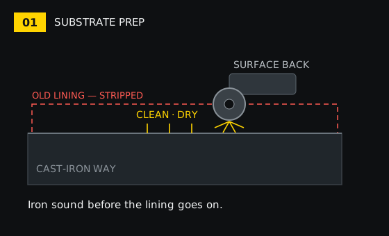
Step 1 — Substrate preparation
Strip the old lining, then bring the iron itself to a sound, clean and dry surface. Scoring, scuffing or picked-up metal has to be dealt with here. A new lining bonded over a damaged way will not restore geometry, and it is the most common way a relining job fails to deliver what was expected.
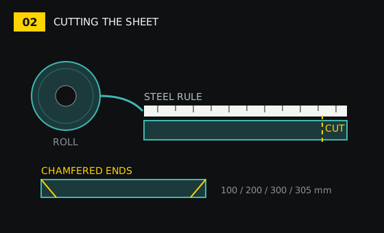
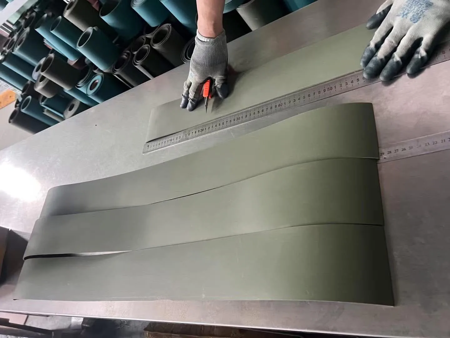
Step 2 — Cutting the sheet
The roll is unrolled, measured against a steel rule, and cut to the strip dimensions for that way. Ends are chamfered so they sit down cleanly rather than standing proud at the joint.
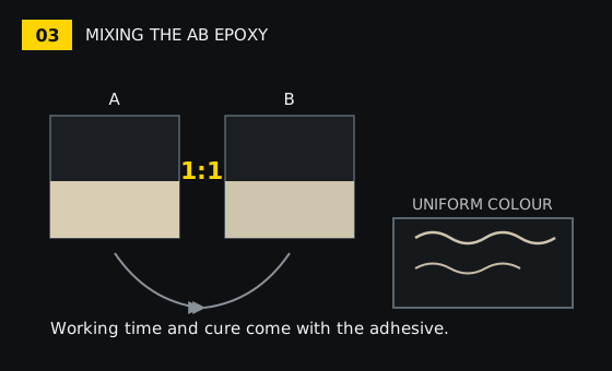
Step 3 — Mixing the AB epoxy
The two components are measured out to the listed AB = 1:1 ratio and mixed thoroughly to a uniform colour. Partly mixed adhesive cures unevenly, and the patch that never fully cures is the patch that lifts later.
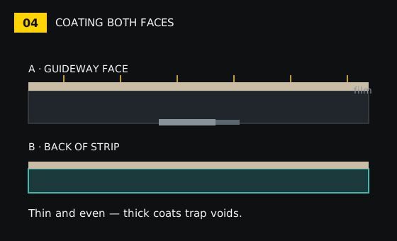
Step 4 — Coating both faces
A thin, even coat goes onto both the guideway surface and the back of the strip. A coat that is uneven or too thick is what produces trapped voids and high spots once the strip is pressed down.
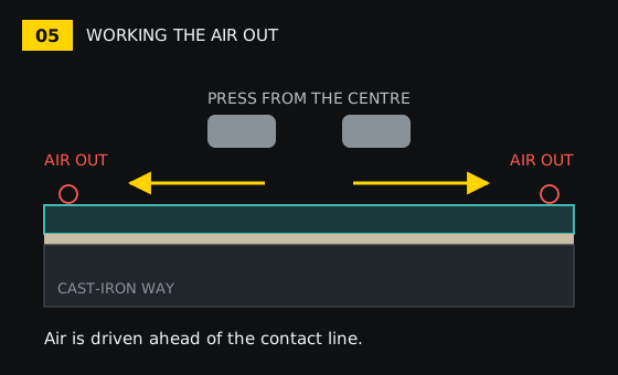
Step 5 — Laying up and working the air out
The strip is laid on and pressed from the centre outwards to both edges. Contact moves outward, so trapped air is driven ahead of the contact line instead of being sealed under the middle of the strip.
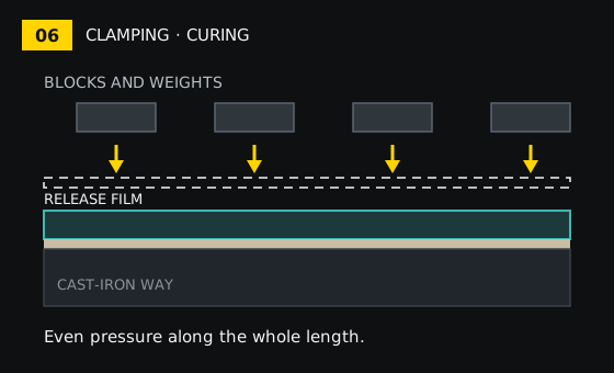
Step 6 — Clamping and curing
A release sheet goes over the strip, then blocks and weights apply even pressure along the whole length while the adhesive cures. Pressure, dwell and cure time follow the adhesive supplied with the batch — both working time and cure move with workshop temperature, so follow that sheet rather than a generic figure.
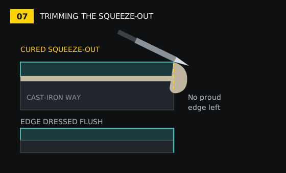
Step 7 — Trimming and cleaning the squeeze-out
Once cured, the excess adhesive is cut back from the edges and the strip edges are dressed. No proud ridge and no loose flash should be left to interfere with the mating member.
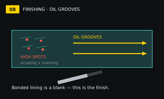
Step 8 — Finishing and oil grooves
The lining as bonded is a blank, not a bearing surface. Hand-scraping, spotting the contact pattern, and cutting the lubricating oil grooves are what bring it to the condition the machine needs. A marking compound such as Tuschierpaste shows where contact actually is, which is how you find the high spots rather than guessing at them.
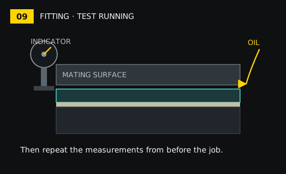
Step 9 — Fitting, assembly and test running
The mating surfaces are matched up, oil is fed through the lubrication system, and clearances are checked with an indicator. Then the measurements recorded before the job are repeated and compared — that comparison, not the machine simply running, is what tells you the work landed.
What relining will not fix
- Wear or scoring in the iron underneath, which has to be dealt with before a lining goes on.
- Errors coming from the screw, the feedback system, or the foundation and levelling.
- A machine that simply needs its lubrication delivery restored.
What we keep in stock
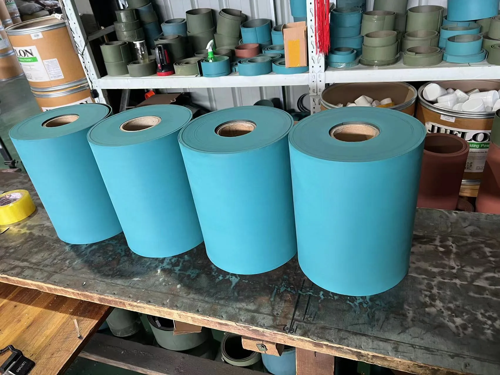
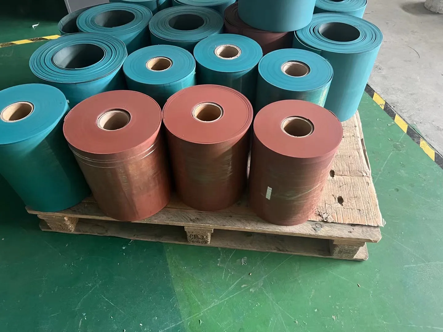
The sheets are held in four listed colours — blue, green, brown and brick red — in widths of 100, 200, 300 and 305 mm, with thicknesses of 0.8–3.2 mm across the listed sheets. OEM sizes are accepted, and the brick red sheet is quoted against the requirement rather than from a fixed list.
Thickness is not a cosmetic choice. It sets how much material has to be machined and scraped away to bring the machine back to geometry, so it is worth settling before the roll is cut rather than after.
The four listed grades: blue sheet · green sheet · brown sheet · brick red sheet.
Adhesive and marking compound
A two-part epoxy adhesive is listed alongside the sheets at AB = 1:1, and a marking compound for fitting and checking work. Ordering the adhesive with the sheet keeps the pair matched to the batch you will actually be using.
Packing and delivery
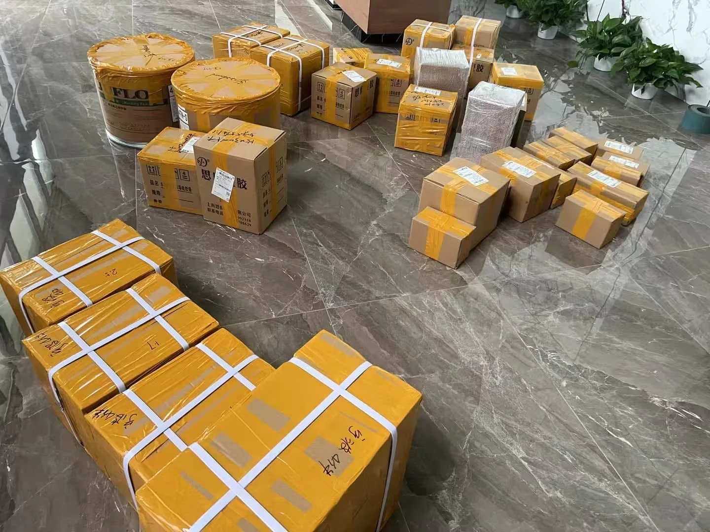
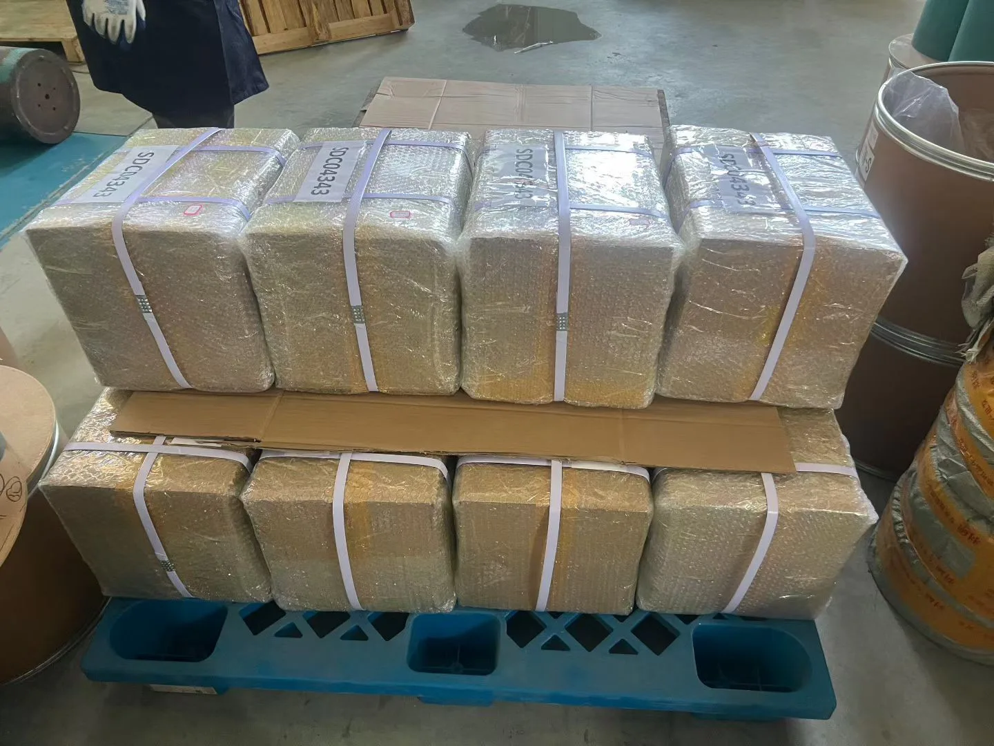
Sheets are packed in cartons, and palletised with stretch film and strapping for export.
If you are not sure
Send us the machine details, the way dimensions and a photograph of the worn surface, and we will confirm what the job needs — the grade, the thickness, and whether the iron has to be dealt with first. Note that final suitability, dimensions, material grade and operating limits need technical review for the specific application.
Material for this class of work: Turcite B sheets, the two-part epoxy adhesive, the marking compound — or send the details and we will come back to you.