CHV- 130A Precision Hydraulic Tooling Machine Vise is supplied as a workholding and fixture components item in the Plain Vise range and is identified for CNC machining-centre and milling-machine workholding. This section expands the available technical information. It supports technical review and part selection; it does not replace a drawing, a machine manual or an application check by a qualified engineer. The product title and the captured attributes remain the primary identification signals, and no performance figure, certification or tolerance class is stated here unless it is present in the captured record.
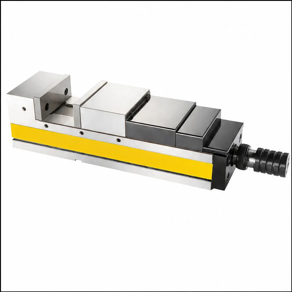 FIG. / PRODUCT VISUAL / 1 VIEWS
Product images are shown for technical review; final compatibility is confirmed before quotation.
TBK-PV-CM-1600396845153
TEBAK CHV- 130A Precision Hydraulic Tooling Machine Vise
CHV- 130A Precision Hydraulic Tooling Machine Vise is a workholding and fixture components item in the Plain Vise range, identified for CNC machining-centre and milling-machine workholding. It locates and holds a workpiece against machining force while keeping the setup repeatable. Common applications include milling, turning, inspection, fixture plates and production changeovers. Key specifications: type: Angle Vise; drive mode: Manual; machinery test report: Provided; video outgoing-inspection: Provided; core components: other; weight (kg): 42; Material: Spheroidal graphite cast iron; Model: TB-CHV-130A; Parallelism: 0.005mm/100m; Hardness: HRC 52-60; Usage: Working- Piece; Weight: 42kg; Keywords: High-precision MC compact Mechanical/Hydraulic Vise/Angle Vise; Selling Units: Single item. Values not listed here, such as tolerance, material grade, load rating or accuracy class, remain unconfirmed until they are checked against a drawing or the machine documentation.
typeAngle Vise
drive modeManual
machinery test reportProvided
video outgoing-inspectionProvided
core componentsother
weight (kg)42
MaterialSpheroidal graphite cast iron
ModelTB-CHV-130A
Parallelism0.005mm/100m
HardnessHRC 52-60
UsageWorking- Piece
Weight42kg
KeywordsHigh-precision MC compact Mechanical/Hydraulic Vise/Angle Vise
Selling UnitsSingle item
APPLICATION CHECKCNC machining-centre and milling-machine workholdingConfirm machine model, interface and drawing before order.
Request this part Ask about an alternativePRODUCT DETAILTECHNICAL INFORMATION
TECHNICAL DETAIL
Product overview. The role of this component is to locate and restrain a workpiece while machining forces, tool access and repeatable setup are managed around the machine table or spindle. In service it works as one part of a larger machine system, so correct performance depends on the relationship between the part, the mating component, the available installation space and the process conditions. Typical applications include milling, turning, inspection, fixture plates, multi-side machining, production changeovers and repeat setups where stable workholding is required. Where the component is used on a moving axis or in a fixture, confirm that the full working envelope is unobstructed and that adjacent parts, guards, cables and tools cannot interfere through the complete travel or clamping range.
Captured parameters and specifications. The record contains the following fields: type: Angle Vise; drive mode: Manual; machinery test report: Provided; video outgoing-inspection: Provided; core components: other; weight (kg): 42; Material: Spheroidal graphite cast iron; Model: TB-CHV-130A; Parallelism: 0.005mm/100m; Hardness: HRC 52-60; Usage: Working- Piece; Weight: 42kg; Keywords: High-precision MC compact Mechanical/Hydraulic Vise/Angle Vise; Selling Units: Single item. The captured material field is Spheroidal graphite cast iron. These values are the specifications currently visible in the captured product data. Where a field is absent, the absence is an open technical item rather than permission to assume a standard value. Confirm the exact model, revision, critical dimensions, tolerance, surface condition, quantity of matched parts and any required accessories before approval.
Model variants in this family. Similar-looking workholding products are usually separated by jaw width and opening, clamping method (screw, hydraulic, pneumatic or mechanical), number of clamping faces, body height, base mounting pattern, jaw type and the zero-point or grid interface they accept. Confirm whether the item is a complete unit or a body only, and whether jaws, stops, screws or mounting bolts are included.
Selection and compatibility review. The most important checks for this item are jaw width and opening range, clamping method, mounting pattern, reference height, workpiece envelope and machine fit. Compare each point with the existing assembly rather than against a similar-looking image, and confirm whether the listed model is a complete assembly, a single replacement component, a set, or an accessory. Where the application involves coolant, chips, dust, vibration, heat or frequent changeovers, include that information in the technical request because it can change the suitable configuration.
Receiving inspection. Inspect the clamping surfaces, screw or cylinder action and all moving joints. Open and close the device through its full range and confirm smooth operation with no binding or looseness. Check reference faces and the base for burrs, dents or paint runs that could sit between the part and the machine table. Keep the protective packaging in place until the part is ready to be installed and record any transit damage before signing for the delivery.
Installation and service considerations. Clean and inspect mating surfaces before installation. Remove damaged fasteners, burrs and contamination that could alter alignment, and follow the machine maker sequence for tightening, adjustment, lubrication and run-in. After installation, check smooth movement, reference position, clamping or cutting stability, abnormal noise, backlash and contact marks. For an electrical or sensing item, isolate power and verify the connector and signal before energizing. These steps are general service guidance; the machine manual and a qualified technician remain the authority for the final procedure.
Fault diagnosis. If a workpiece lifts or shifts during cutting, check clamp force, jaw contact pattern, jaw wear and whether the clamping point is supported directly above the fixture base. If repeatability is poor across changeovers, look for chips trapped on locating faces, worn jaw steps or a base that is not seated flat. Record the observed symptom together with any error code, noise, temperature reading or dimensional drift before removing the part, because that information shows which characteristic of the component actually matters in this installation.
Maintenance and wear monitoring. Clean and lightly lubricate the screw, guideways and sliding faces on a schedule that matches the machine environment. Remove chips from locating surfaces after every changeover. Check jaw wear regularly, especially where hard materials are machined, and confirm that clamping force has not drifted. Replacement should follow the original installation, alignment and adjustment sequence rather than being treated as a simple part swap.
Documentation and traceability. Keep the product ID, machine model, installation position, installation date, measured critical dimensions and any drawing revision together with this part record. Where the item is matched to a specific axis, station or fixture, record that reference as well, because a later replacement ordered from a photograph alone can be mistaken for a similar variant. If the part is replaced as part of a repair, note the reason for replacement and any adjustment made during fitting so a repeat problem can be distinguished from normal wear.
What to confirm in an inquiry. Include the product ID TBK-PV-CM-1600396845153, the required quantity, machine brand and model, interface or mounting information, a drawing or clear photographs, the workpiece or application material, the operating environment and the dimensions that matter most. Ask for a current technical drawing, available variants, confirmed material, complete contents, inspection information and compatibility notes before treating the item as a final match.
SPECIFICATION INPUT
Exact fit starts with the machine.
Specifications are listed with the part. Confirm machine model, interface, material and drawing before quotation.
INPUT / 2D + 3D DRAWINGCHECK / INTERFACE + MATERIALOUTPUT / QUOTATION ROUTE